Every control, every warning, every service interval — organized, searchable, and ready whenever you need it. From the cab to the shop bench, this manual works the way you do.
ISO 3600 Compliant
Choose your workspace
Open the Operator Manual or jump straight into the Parts System.
Both tools now share one Summit shell, one brand language, and one search bar — but each workspace keeps its own navigation so the experience feels cleaner and easier to use.
◆ Own · Step 03
Register your tractor to activate warranty.
3-year full warranty · 7-year limited powertrain · service network · DIY support. Takes just a few minutes.
On behalf of the Summit Tractors team, we thank you for the confidence that you have in the Summit Tractors™ brand and our products, the retail store where you made your purchase, and our family of U.S. and international tractor, attachment, tires & wheel, and accessories manufacturing partners.
We realize that you have many choices when it comes to purchasing compact utility tractor equipment, and we endeavor to exceed your expectations for the overall value, quality, and productivity of the equipment — and through our customer and equipment service network.
Before using your tractor, we highly recommend that you and any other person that will use your tractor read the enclosed tractor operator's manual thoroughly, with a particular focus on the SAFETY related information in Chapter 2.
To properly maintain your equipment, you will find very useful information related to routine checks and periodic maintenance in Chapter 5. If you want to perform your own maintenance, visit summittractorsattachments.com for parts. If you'd like one of our Service Dealers to handle it, use the locator on summittractors.com, or call 770-209-3390 and press 2.
Again, we thank you and welcome you to the family of Summit Tractors™ owners.
— The Summit Tractors Team
Using This Operator Manual
This manual is an important part of your tractor and it should be kept with the tractor at all times. Reading this manual will help you and others avoid personal injury or damage to the tractor. Information provided in this manual will help you to use the tractor in the safest and most effective way.
If you have an attachment, use the safety and operating information in the attachment operator's manual along with the tractor operator's manual to operate the attachment safely and correctly. The tractor shown in this manual may differ slightly from your tractor but will be similar enough to help you understand our instructions.
Throughout this manual, the use of terms left side, right side, front side and rear side must be understood to avoid confusion:
Left & Right
Sides of the tractor when facing the direction of forward travel
Front
The radiator end of the tractor
Rear
The drawbar end of the tractor
Identification — Serial Numbers & Plates
Always specify the tractor chassis and engine serial numbers when you need replacement parts. This will facilitate correct and faster delivery from the authorized servicing dealer.
Chassis Serial Number
The chassis number is punched on the right side of the front axle bracket of the tractor. Should you find the number difficult to read, you will also find it on the statutory plate.
Engine Serial Number
The engine serial number is stamped on the upper side of the fuel injection pump installation part, located on the right side of the cylinder block. For easy reference, the engine serial number is also mentioned on the valve cover of the engine (via a sticker).
Statutory Plate
The chassis number is also engraved on the statutory plate. The statutory plate is located on the left-hand side fender.
ROPS Certificate Plate
The ROPS certificate plate is riveted on the ROPS (Roll-Over Protection Structure). Information about the ROPS serial number and tractor model is engraved on the plate.
◆ Activate Your Warranty
Haven't registered your TX25H yet?
Warranty service requires official registration. It only takes a few minutes.
Keep your chassis & engine serial numbers handy so they're one click away whenever you call your dealer or order parts. This form is for quick reference only — stored on this device. Official warranty activation happens on summittractors.com.
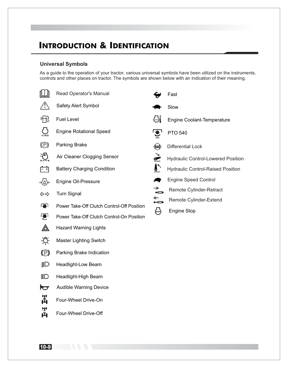
Universal Symbols
As a guide to the operation of your tractor, 23 universal symbols are used on the instruments and controls. Below is the complete legend — swipe through the cards or view the full reference page.
Icon style
Read Operator's Manual
Reminder to consult this manual.
Safety Alert
Triangle — alerts you to risks.
Fuel Level
Fuel tank indicator.
Engine RPM (n/min)
Engine rotational speed.
Parking Brake
Circled "P" — engaged condition.
Air Cleaner Clogging
Filter requires cleaning.
Battery Charging
Battery + / − terminals.
Engine Oil Pressure
Oil lubrication warning.
Turn Signal
Left / Right directional arrows.
PTO Clutch — Off
Power take-off disengaged.
PTO Clutch — On
Power take-off engaged.
For the complete 23-symbol reference — including Hazard Warning Lights, Master Lighting Switch, Headlights, Horn, 4WD On/Off, Fast/Slow, Engine Coolant Temperature, PTO 540, Differential Lock, Hydraulic Control, Engine Speed Control, Remote Cylinder, and Engine Stop — see the original reference page below.
Page 10 · Complete Universal Symbols reference, as shown in the original operator manual.
This chapter contains life-safety information and your warranty terms. Every operator of this tractor — new or experienced — must read and understand this chapter in full before first use, and refresh annually.
Limited Warranty for New Summit Tractors
General Provisions
The warranties described below are provided by IT USA ("Summit") to the original purchasers of new SUMMIT brand tractors ("Equipment") from any SUMMIT retailer store location. Under the warranties provided by SUMMIT, SUMMIT will repair or replace, at its option, any covered part which is found to be defective in material or workmanship during the applicable warranty term.
Warranty service must be performed at a service center authorized by SUMMIT to service the type of Equipment involved, which will use only new or re-manufactured parts or components furnished or sourced by SUMMIT. Warranty service will be performed without charge to the purchaser for parts and labor.
The purchaser will be responsible for any service call and/or transportation of any Equipment or Product to and from the service center's place of business, and for any service and/or maintenance not directly related to any defect covered under the warranties below. These warranties are transferable provided an authorized SUMMIT service center is notified of the ownership change, and SUMMIT approves the transfer in writing.
What is Warranted?
Subject to the Length of Warranty Chart provided in the "LIMITED WARRANTY FOR NEW SUMMIT TRACTORS" warranty statement (available at www.summittractors.com), all parts of any new SUMMIT Equipment — except tires, wheels, starter motor, battery and alternator (which are warranted under separate documents) — are warranted for the number of months or operating hours specified.
Summit Tractors Powertrain Warranty
Engine
Cylinder block, cylinder head, valve covers, oil pan, timing gear covers, flywheel housing, emission control components, and all parts contained therein.
Powertrain
Transmission, transmission case, differential and axle housing, MFWD front axle assembly, and all parts contained therein.
Exclusions
The Powertrain Warranty does not include external drivelines, or steering cylinders — including but not limited to the HST assembly (HST pump), HST damper plate, and HST damper assembly.
What is Not Warranted
SUMMIT is not responsible for the following:
Used equipment.
Any Equipment that has been altered or modified in ways not approved by SUMMIT, including but not limited to setting injection pump fuel delivery above SUMMIT or manufacturer specifications.
Depreciation or damage caused by normal wear and tear, lack of reasonable or proper maintenance, failure to follow operating instructions, misuse, lack of proper protection during storage, or accident.
Normal maintenance parts and service including but not limited to light bulbs, filters (oil, fuel, air and hydraulic), belts, motor brushes, brakes, fuses and switches, clutch linings, engine tune-up, wheel alignment, blade sharpening and lubrication.
Maintain Your Records
Purchasers have a duty to maintain maintenance records. SUMMIT may request documentation of maintenance. Failure to maintain and provide maintenance records upon request shall void all warranty and prohibit all warranty claims.
Securing Warranty Service
◆ Step 1 — Register First
Your warranty starts with registration.
Warranty coverage is only available to registered owners. Register now if you haven't already.
Once registered, to secure warranty service the original purchaser (or a subsequent purchaser to whom the warranty has been properly transferred) must:
Report the product defect in writing to an authorized Summit Tractors service center and request repair within the applicable warranty period.
Present written evidence that the warranty registration has been completed and indicate the warranty start date.
Bring the Equipment to an authorized SUMMIT service center within five (5) business days and prior to the expiration of the applicable warranty period.
Emission System Warranty Statement
Summit warrants to the purchaser that at the time of initial sale, the engine used in the Summit brand tractor is designed, built and equipped to conform to all applicable regulations of the US Environmental Protection Agency (EPA), and that the engine is free of defects in materials and workmanship that may cause it to fail to conform with EPA regulations during its warranty period.
Emission Warranty Parts List
Air Induction System: Intake manifold.
Thermal Reactor System: Exhaust manifold.
Fuel Injection System: Fuel supply pump, injector, injection pipe, cold advance timer, fuel injection pump, any device used to collect particulate emissions, control device enclosures and manifolds.
Miscellaneous Items: Closed breather system; hoses*, clamps*, fittings*, tubing*; gaskets, seals; engine manufacturer-supplied wiring harnesses & electrical connectors; air cleaner element*; fuel filter element*; emission control information labels. (*Until the first scheduled replacement point.)
Emission Warranty Exclusions
Non-performance of scheduled maintenance.
Use of the engine/tractor in a manner for which it is not designed.
Abuse, neglect, improper maintenance, or unapproved modifications/alterations.
Accidents for which Summit has no responsibility or acts of God.
Use of fuel not recommended by Summit.
Safety Sign Levels
The safety alert symbol means ATTENTION! BECOME ALERT! YOUR SAFETY IS INVOLVED! Any of the following symbols on your machine or in this manual alert you to the potential for personal injury. Follow recommended precautions and safe operating practices.
Danger
Indicates an immediate hazardous situation which, if not avoided, can result in death or very serious injury.
Warning
Indicates a potentially hazardous situation. If the instructions or procedures are not correctly followed, it could result in death or very serious injury.
Caution
Indicates a potentially hazardous situation, which if not avoided, may result in minor injury.
Important
Indicates that equipment or property damage could result if instructions are not followed.
Note
Indicates important information or information which is useful for tractor operation.
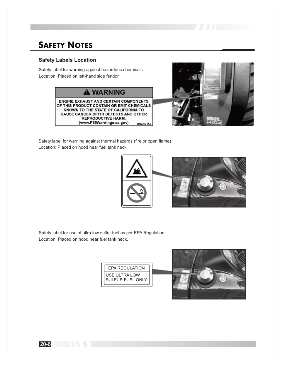
Safety Labels on the Tractor
Safety labels are placed at critical locations on your TX25H. Know each one and keep them legible — replace any that become worn or damaged.
Hazardous Chemicals, Thermal & ULSD Fuel
Left fender & hood by fuel tank neck. Use Ultra Low Sulfur Diesel Only.
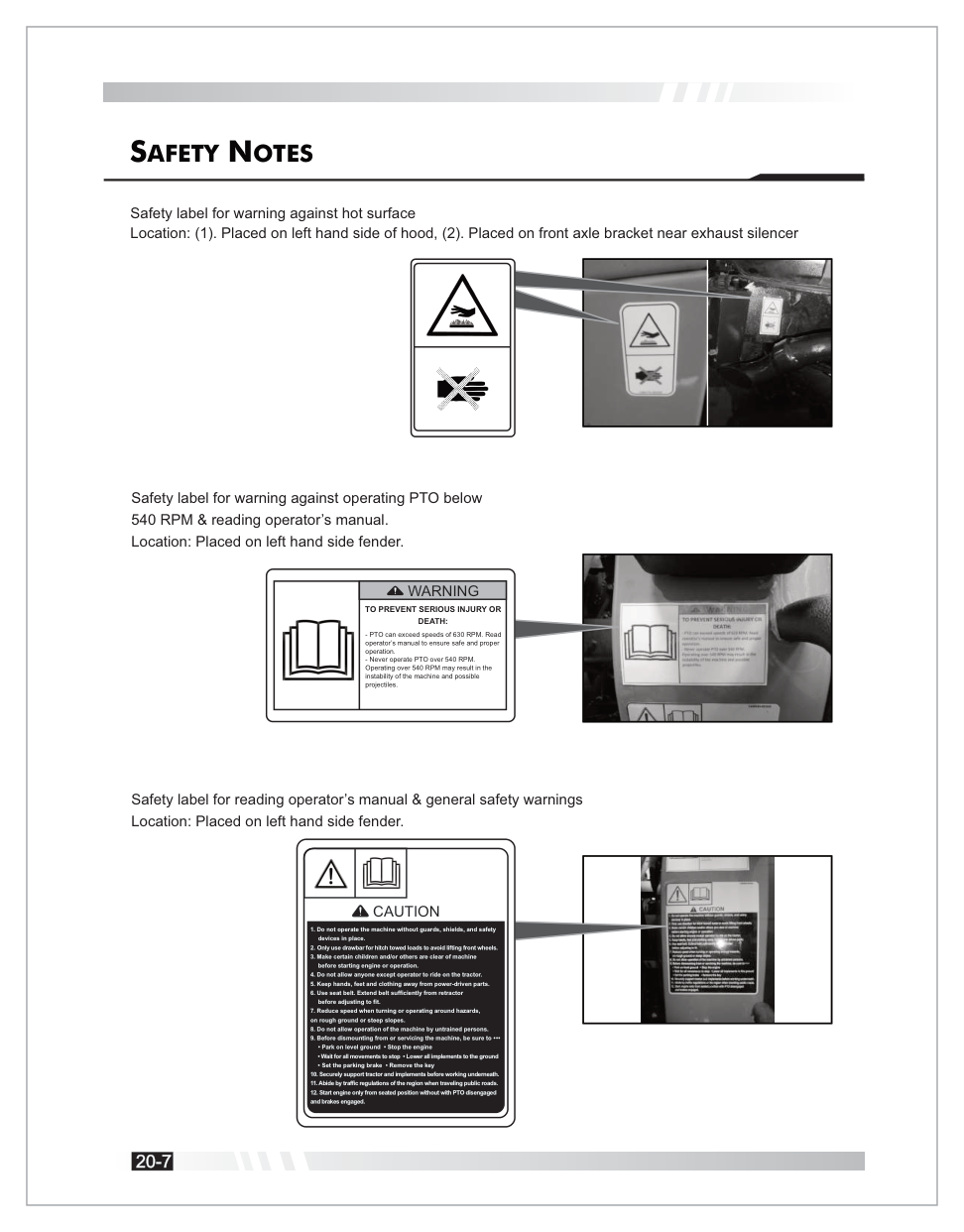
Hot Surface, PTO & General Safety
Hood, front axle, left fender. Never operate PTO over 540 RPM.
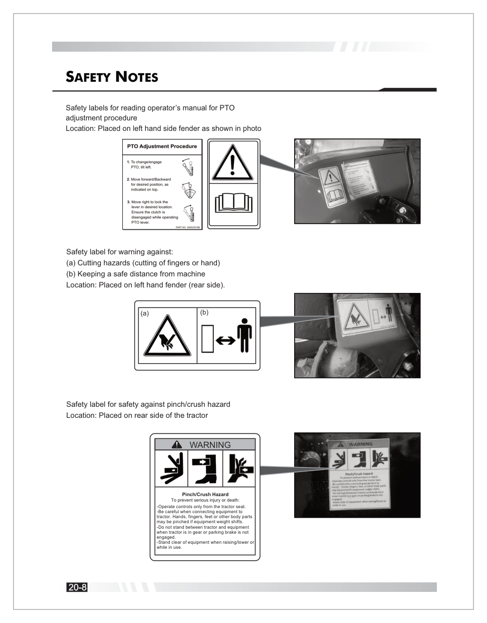
Cutting, Safe Distance & Pinch/Crush
Rear fender & rear of tractor. Stand clear of implements.
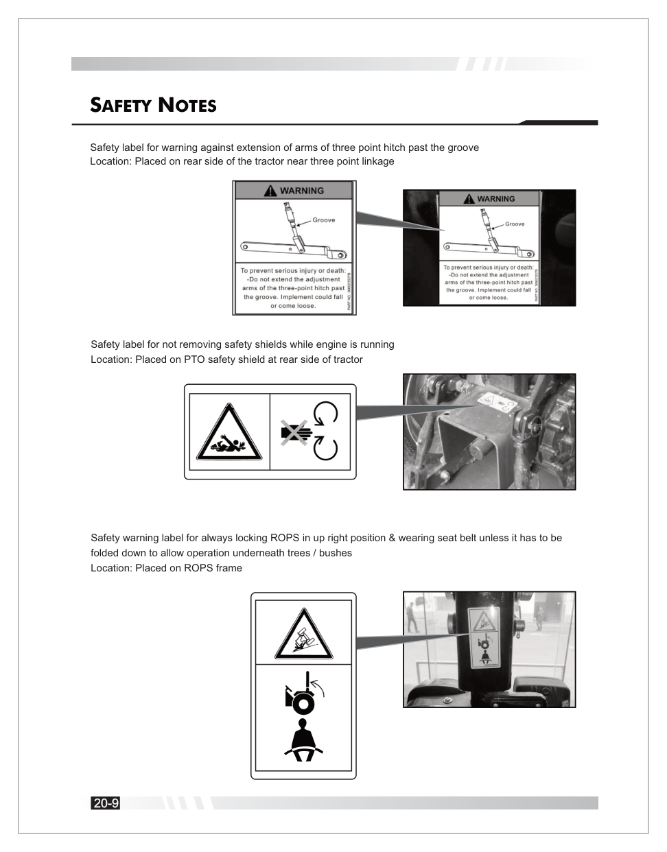
3-Point Hitch & ROPS / Seat Belt
Rear linkage area & ROPS frame. Always wear belt with ROPS upright.
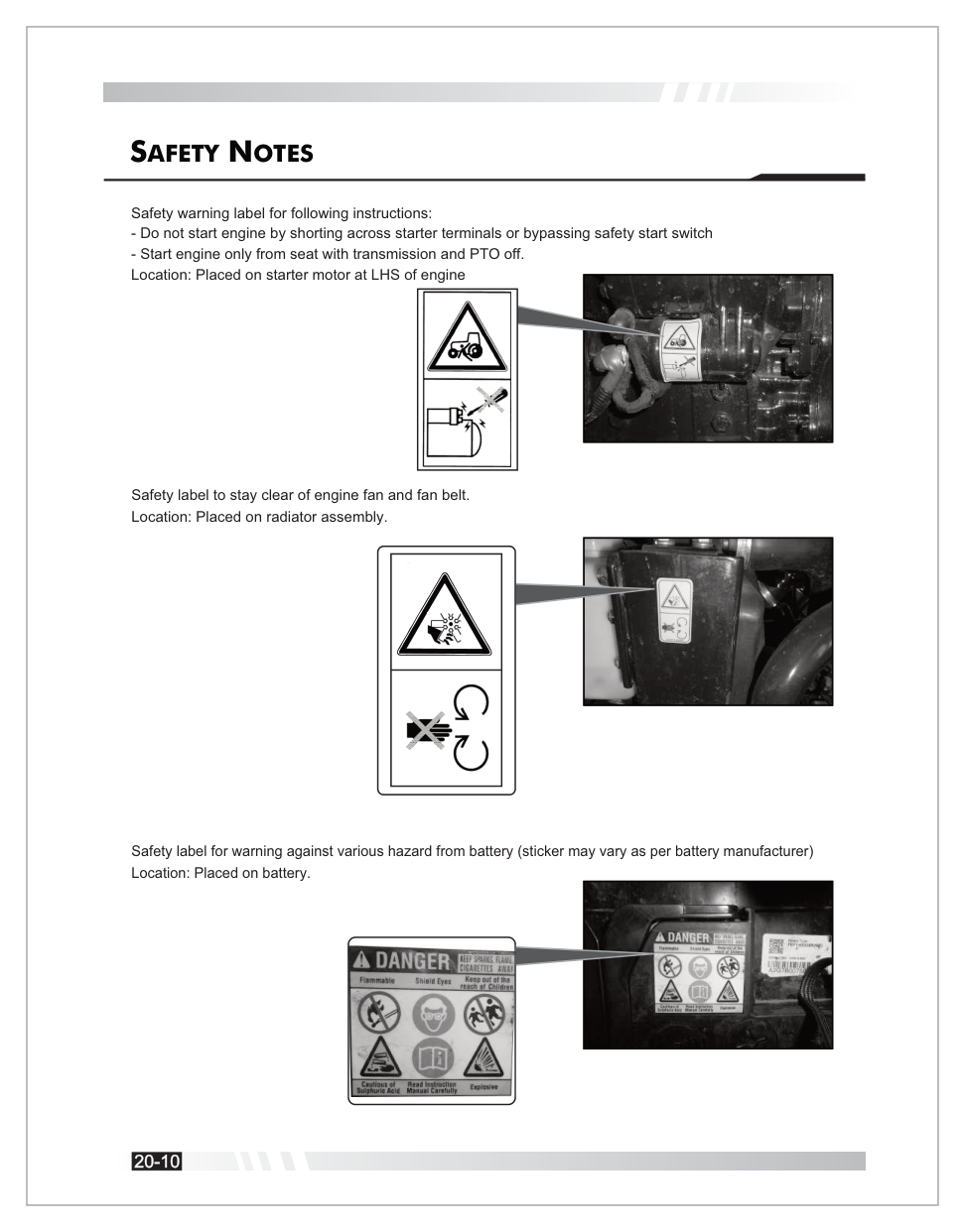
Starter, Engine Fan & Battery
Start only from the seat. Stay clear of fan. Battery acid hazard.
PTO — Critical Warning
TO PREVENT SERIOUS INJURY OR DEATH: PTO can exceed speeds of 630 RPM. Read the operator's manual to ensure safe and proper operation. Never operate PTO over 540 RPM. Operating over 540 RPM may result in the instability of the machine and possible projectiles.
General Safety (Caution Label — Left Fender)
Do not operate the machine without guards, shields, and safety devices in place.
Only use the drawbar for hitch-towed loads to avoid lifting front wheels.
Make certain children and others are clear of the machine before starting or operating.
Do not allow anyone except the operator to ride on the tractor.
Keep hands, feet, and clothing away from power-driven parts.
Use the seat belt. Extend it sufficiently from the retractor before adjusting to fit.
Reduce speed when turning or operating around hazards, on rough ground, or steep slopes.
Do not allow untrained persons to operate the machine.
Before dismounting or servicing: park on level ground; stop the engine; wait for all movements to stop; lower all implements; set the parking brake; remove the key.
Securely support tractor and implements before working underneath.
Abide by traffic regulations of the region when traveling public roads.
Start the engine only from a seated position with PTO disengaged and brakes engaged.
Prepare for Safe Operation
Protect yourself by wearing:
A hard hat
Safety glasses, goggles, or face shield
Hearing protection
Respirator or filter mask
Inclement weather clothing
Reflective clothing
Heavy gloves
Safety shoes
Warning
DO NOT wear loose clothing, jewelry, or other items — and tie up long hair — which could catch on controls.
Safe Operation Notes
Before Operating
Read all safety instructions. Do not allow unauthorized modifications.
Driving
Watch for obstacles; avoid rollovers by driving at safe speeds; lock brake pedals together for road transport; keep in gear when going downhill.
Starting
Warn bystanders; use "three-point contact" when mounting; ensure ventilation; never operate in a closed building.
Riders
Do not allow riders on the tractor.
Tipping
Stay alert for holes/rocks; slow down for sharp turns; back out of ditches to avoid backward tips.
Overturning
If overturning, hold the steering wheel firmly and DO NOT attempt to leave the seat until the tractor has come to rest.
Parking
Lower all equipment, stop engine, and remove key.
Safety Starter Switch
Do not bypass the clutch-operated safety switch.
High-Pressure Fluids
Escaping fluid can penetrate skin. Seek medical help immediately if injected — failure to remove the fluid surgically within hours can lead to serious injury or death.
Battery Hazards
Avoid sparks and open flame. Sulfuric acid is poisonous and causes severe burns. Always wear eye protection when servicing the battery.
Fuel & Static Electricity
Fuel is highly flammable — stop the engine before refueling. Ensure refueling systems are properly grounded, especially when using Ultra-Low Sulfur Diesel (ULSD), which has decreased conductivity.
Fire Prevention
Regularly clean debris (hay, crop material) from the engine and exhaust. In case of fire, stop immediately, get off, and call the fire department.
Seat Belt & ROPS
Use the seat belt only when the ROPS is in the upright position. Do NOT use the seat belt if the ROPS is folded for low-clearance work.
Forestry Use
Use is limited to transport and stationary work. Applications like loading require FOPS/OPS structures.
Safety While Operating Loader Attachments
Only authorized and trained personnel over 18 years old.
Check all functions before use.
Check weight/nature of load and ground stability.
Do not use on steep slopes.
Do not lift or transport people or use as a working platform.
Never transit or halt under suspended loads.
Safety From Lightning Strike
As soon as you hear thunder, shut off and put away equipment and move indoors. A sturdy building provides the best protection.
The TX25H features the following primary controls. Familiarize yourself with each before operating. Select a control card to jump to the matching operating section.
Click any indicator on the dashboard to learn what it means and what to do when it illuminates.
Interactive Dashboard
Click any gold hotspot above to learn what that indicator means and what to do when it illuminates.
Indicator Details
Parking Brake Indicator
Glows when the parking brake lever is engaged.
Parking brake indicator location
Battery Charge Indicator
Indicates charging status. If it glows while the engine is running, the charging system is defective or the battery is draining.
Ignition
Engine
Indicator
Meaning
ON
OFF
Glow
OK
ON
OFF
Off
Charging system/battery defective — see electrician
ON
Running
Off
Battery charging normally
ON
Running
Glow
Charging system defective — have checked
Battery charge indicator
Air Cleaner Clogging Indicator
Glows when the air filter is clogged. Clean immediately with air pressure.
Caution
Operating with a clogged air filter reduces power and can damage the engine. Clean the filter element as soon as this indicator illuminates.
Air cleaner clogging indicator
Turn Indicators
Separate lamps for Left and Right turn signals.
High Beam Indicator
Glows when headlights are in high-beam mode.
Cold Start (Glow Plug) Indication
Glows when the ignition heater is active (second key position). Wait until the indicator turns off before cranking the engine.
Engine Oil Pressure Indicator
Danger — Stop Immediately
Indicates low lubricating oil pressure. If it glows, stop the engine immediately, check oil levels, and do not operate until resolved — continued operation will cause catastrophic engine damage.
Temperature Gauge
Note: The dashboard photo above does not clearly show a dedicated temperature-gauge face, so this item is kept as a text-only reference instead of a dashboard hotspot.
Green zone is normal; Red zone indicates overheating. If it enters the red zone, idle the engine, then shut it off and check coolant levels and fan belt.
PTO Monitor Lamp
Turns ON when the PTO clutch is engaged.
Trailer Turn Indicator
Indicates the status of trailer turn signals via the 7-pin socket.
Engine RPM & Hour Meter
Shows engine speed in RPM and total hours worked. The hour reading depends on engine RPM.
Work Lamp Indicator
Glows when the rear work lamp is ON.
Fuel Gauge
Shows fuel level. If in the red zone, refill immediately.
Avoid Air Lock
Maintain at least 1.6 U.S. Gallons (6 Liters) of fuel to avoid air-locking the fuel system.
Cruise On-Off Indicator
Glows when the cruise control system is active.
Dashboard Controls
Hazard Warning Light Switch
Blinks all four indicators for mechanical defects or emergency situations.
Combination Switch
Controls:
Horn — press.
Side Indicators — move lever Left/Right.
Headlights / Parking lights — rotate clockwise through 3 positions: Parking → Low Beam → High Beam.
Ignition Switch
OFF
Disconnects electrical systems; key can be removed.
ON / HEATER
Functional position for warning lights and glow plug pre-heat.
START
Cranks the engine. Do not engage for more than 5–8 seconds at a time.
PTO ON-OFF Switch
Press for 3 seconds to engage the PTO; press again to stop.
Cruise Control Switch
Upper part activates; lower part deactivates.
Electrical Components
Fuse Box
Mounted on the radiator bracket.
Never Bypass a Fuse
Always replace blown fuses with the specified rating. Never use wire or a larger-ampere fuse — doing so creates a fire hazard and will damage the electrical system.
Battery
Located at the front of the tractor on the front axle bracket, accessible by opening the hood.
Seven-Pin Socket
Mounted on the license plate for trailer connections.
Pin 1
Left Turn
Pin 2
Fog / Aux
Pin 3
Ground
Pin 4
Right Turn
Pin 5
Right Parking
Pin 6
Brake Light
Tractor Lights
Head Lights — projector lamps for better focus.
Tail Lights — include brake and turn signal indications.
Registration Plate Light — located at the rear.
Work Lamp — adjustable lamp at the rear.
Turn / Hazard Signal Lights — fitted on the ROPS.
Operator's Seat
The seat is part of the ROPS safety zone and features:
Weight Adjustment
Knob at the back · Range: 110.2 – 264.5 lbf.
Horizontal Adjustment
Lever (1) to slide forward/backward.
Vertical / Suspension Adjustment
Knobs (2) and (3) for height and suspension.
Armrest Inclination
Knob (5) to adjust angle.
Height Adjustment
Requires loosening bolt (A) and knobs (B1/B2) at the rear lower side.
Seat Belt
Must always be used when the ROPS is in the upright position.
This tractor is equipped with an audible and visible alarm that alerts the operator when leaving the driving position without the parking brake applied. The alarm activates when the operator is detected out of the driving position and the parking brake is not applied. The time-out of the alarm is 5–7 seconds. The alarm deactivates when the operator returns or the parking brake is applied.
Gears
Seat
Brake
Buzzer
Engine
Neutral
Empty
OFF
Continuous
Stops within 1 sec
Neutral
Empty
ON
—
No shut-off
Engaged
Empty
OFF
Continuous
Stops within 1 sec
Engaged
Empty
ON
—
Stops within 1 sec
Boarding & Leaving the Tractor
Boarding
Always board from the left-hand side where a footrest is provided. Be careful not to contact any levers.
Leaving
After stopping the tractor, leave from the left side.
Three-Point Contact
Always use three-point contact (two hands and one foot, or one hand and two feet) when mounting or dismounting.
Starting the Engine
The ignition switch has four positions:
OFF
Power cut off; key can be removed.
ON
Power supplied to electric circuits.
HEAT
Intermediate position to heat glow plugs for cold starts.
START
Cranks the engine.
Glow Plug Pre-heating Times
At -4°F
21–27 sec
At 32°F
~8 sec
At 68°F
~4 sec
At 176°F
1.5–3.5 sec
Note
If the engine is not cranked after pre-glow, the controller keeps plugs on for an additional 12 seconds.
Normal Starting Procedure
Engage parking brake.
Gear shifter and Low/High selector in Neutral.
Press clutch pedal fully (safety switch).
Check PTO lever is in neutral.
Turn key to ON → HEAT → START.
Cold Weather Starting (Below 32°F / 0°C)
Use the "Heat" position for a few seconds before "Start." If it fails, wait 5–10 seconds and repeat.
Battery Sizing
For temperatures below 14°F (-10°C), use a battery with more than 700 CCA.
Breaking In
Do not subject the tractor to loads greater than normal working life.
Engage low gears when towing heavy loads.
Check all screws, nuts, and bolts regularly for tightness.
Run in clutch discs correctly to ensure prolonged life.
Turning Off the Engine
Turn the engine accelerator to the idle position.
Stop the engine by turning the starting key to the "OFF" position.
Opening & Closing the Hood
Opening
Pull the knob at the front left side until it clicks. The gas spring will assist in lifting it to the preset height.
Closing
Gently lower the hood and press until the lock engages.
The under-hood muffler is fitted inside the hood for better aesthetics, vision, and sound muffling.
Speed Control Pedals (HST)
Pedal A
Forward direction.
Pedal B
Reverse direction.
Warning
Do not shift between forward and reverse suddenly in high range. This may damage the mechanism or cause injury.
Cruise Control (HST)
Engaging
Press forward pedal to desired speed, then push the cruise control switch.
Disengaging
Push the switch "OFF" or press the brake pedal.
Important
Do not press both speed pedals while cruise is engaged. Disengage while turning.
2WD / 4WD Lever & Hi-Low Lever
2WD / 4WD
2WD
Pull lever (C) upward — for road operation.
4WD
Push lever (C) downward — for field operation.
Hi-Low Lever
Neutral
Middle notch.
High Range
Shift toward the back of the tractor.
Slow Range
Shift toward the front of the tractor.
Hand Throttle Lever
Push up to increase engine speed; pull down to decrease. Used for field applications.
Differential Lock
Press pedal (E) to rotate both wheels at the same speed.
Important
Use the differential lock only in a straight line. Disengage when turning.
Warning
Do not apply if speed is over 3.73 mph (6 kmph).
PTO Operation
The PTO (Power Take-Off) drives rear-mounted and mid-mounted implements.
PTO On-Off Switch
Press for 3 seconds to engage; re-press to stop.
PTO Speeds
Mid PTO
2100 RPM @ 2438 engine RPM
Rear PTO
540 RPM @ 2451 engine RPM
PTO Safety
Engine will not start if PTO is ON. Engine shuts off if the operator leaves the seat with PTO engaged and parking brake released. Never operate the PTO without the master shield (B) in place. Stay clear of rotating shafts.
Hydraulics & Power Steering
Hydraulic Coupling Devices
Equipped with one double-acting (1DA) direction control valve (DCV) and Quick Release Couplers (QRCs) at the rear. Use the DCV lever to control attached implements.
Power Steering
Equipped with a 6.7 CC pump and 40 CC steering unit. Power steering function stops when the engine is shut off.
Transport Lock (Response Valve)
Located on the front end of the hydraulic rear cover. Fully tighten to close/lock the implement height during transportation for safety.
Service & Parking Brakes
Service Brake
Located on the left side.
Parking Brake
Located below the seat. Pull up to engage. To disengage, press sleeve (A) forward and push the lever down.
Important
Driving with the parking brake partially engaged damages internal components.
Wheels & Tires
Tire Inflation Pressure
Front Tires
20–22 P.S.I.
Rear Tires
14–16 P.S.I.
Wheel Hardware Torque
Front Wheel Rim
53 lbf-ft (72 Nm)
Rear Wheel Rim
103 lbf-ft (130 Nm)
Load-Carrying Capacity — Tire Combinations
Configuration
Front
Rear
Goodyear R14T
23×8.50-12 · 1,230 lbs
12-16.5 · 2,760 lbs
Standard Agricultural
6.00-12 · 881 lbs
8.3-20 · 1,543 lbs
Heavy Agricultural
7-14 · 1,510 lbs
8.3-24 · 2,061 lbs
Industrial / Turf
23×8.5-12
33×15.5-16.5
Three-Point Linkage
Used for mounting implements. Includes adjustable lift rods, top link, and lower links.
Max Lifting Capacity
661.39 lb (300 kgf)
Measurement Point
24" from lower link ends
Warning
Stay clear of the linkage area during attachment/detachment. Keep hands, feet, and bystanders away.
Roll-Over Protection Structure (ROPS)
Normal Operation
Always use in the upright position with a seat belt.
Folding the ROPS
Remove R-pin and pin (2), fold ROPS backward until it rests on the stopper, and reinstall pins. Refold upright as soon as clearance allows.
Danger
A tractor overturning without ROPS can result in death. Do not attach chains to ROPS for pulling — always pull from the drawbar.
Following this maintenance schedule — and keeping dated records of every service — is a warranty requirement. Maintain logs at Chapter 8 · Service Record or use your Summit Owners App.
Maintenance Schedule
The schedule applies to normal conditions. Service more frequently in muddy or dusty environments. Beyond 1,500 hours, repeat the cycle every 250 hours.
In-app service video
◆ Walkthrough Video
Your 50-Hour Service — Watch Before You Start
Watch the full 50-hour service walkthrough right inside the manual before you begin filter, fluid, and inspection work.
Legend: C = Check · CA = Adjust · CL = Clean · CP = Fill · CT = Tighten · R = Replace · W = Wash · G = Grease
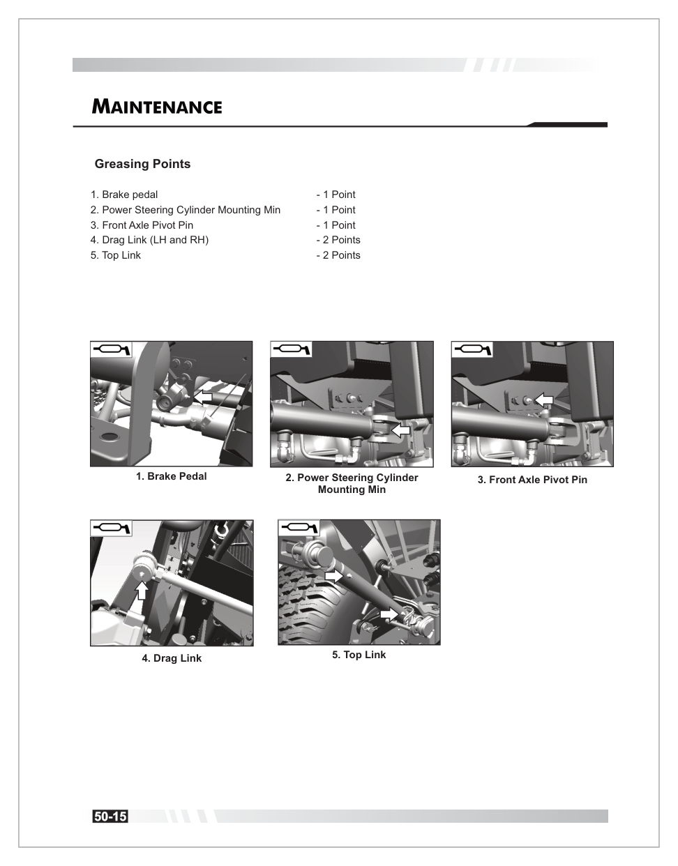
Parts & Diagrams
Fuel-system parts at your fingertips
Filter, tank, and pipe assemblies linked directly to the service content so owners can identify what they are looking at before ordering or calling a dealer.
Complete technical reference for the Summit TX25H Hydrostatic Tractor. All dimensions & specifications are for guidance only and may be updated without prior notice.
A dedicated service workspace tied directly to the TX25H operator content. Search assemblies, inspect part numbers, and pull up diagram pages for a clearer service reference.
114 assemblies1,111 part rows185 diagram pages
Built for owners and techs
Search first. Visual-check second. Order smarter.
Instead of sending customers back into a long PDF, this browser keeps the parts extract and the diagram previews together. Start with a maintenance system, jump into an assembly, then confirm with the diagram image.
Search the Parts System right from the parts workspace.
Jump straight to a part number or an assembly without hunting through the full browser first.
Recommended service assemblies
These collections focus on the assemblies customers are most likely to need while following the operator manual: fuel, cooling, air intake, oil service, hydraulics, PTO, braking, steering, and electrical references.
Assembly browser
Select an assembly
Choose one from the left to load the diagram preview, page references, and part list.
If the standalone preview image does not load on this host, the in-app PDF page appears here instead. When printing from the PDF viewer, choose Custom pages and print only the current page.
Diagram preview image could not be loaded from this host, so the in-app PDF page is shown below instead.
Why this helps
Use the diagram preview to match the service area visually before ordering, removing, or discussing the component with a dealer.
Part list
Part number
Description
Page
Retail price
Dealer cost
Action
Parts basket
Saved parts for this job
Collect parts as you browse, attach customer and claim details, and save the basket locally for export or handoff.
0line items
0total quantity
—retail total
—dealer total
Saved locally in this browser
Ready for the next step
Take this basket straight into ordering or service prep.
Use the official Summit parts portal for ordering, and keep the 50-hour service walkthrough handy while you verify filters, fluids, and service points.
No parts added yet. Use the Add button in the part list to build a saved basket.
Internal tools
Parts admin
Hidden local editor for internal parts maintenance. Import a full list, merge in new assemblies, upload new diagram previews, export the current parts data, or update one part at a time.
Import / export
Shortcut: Ctrl + Alt + A. Full imports accept JSON, JS assignment files, or CSV files using the parts.csv columns. Assembly imports use the same formats and merge new assemblies into the current local dataset.
Diagram files are stored locally in this browser. Use filenames like 01110A-1-1_page12.png, or select an assembly first and use files like page12.png.
Admin mode is local to this browser until you export the updated parts data.
Edit selected part
Select an assembly row, then open admin mode to edit it.